


In the daily lives and industrial processes, various applications demand different forms of electrical energy—high voltage for efficient transmission, low voltage for safety, and both AC and DC currents. To facilitate this seamless conversion between different forms of electrical energy, various power conversion technologies come into play.
Let's explore several fundamental power conversion devices and their operating principles.
1. Transformer
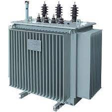
Transformer
A transformer generally refers to a device that either steps up or steps down alternating current (AC) electricity. When AC electricity passes through a coil, it generates an alternating magnetic field, which in turn induces an electric current in another coil.
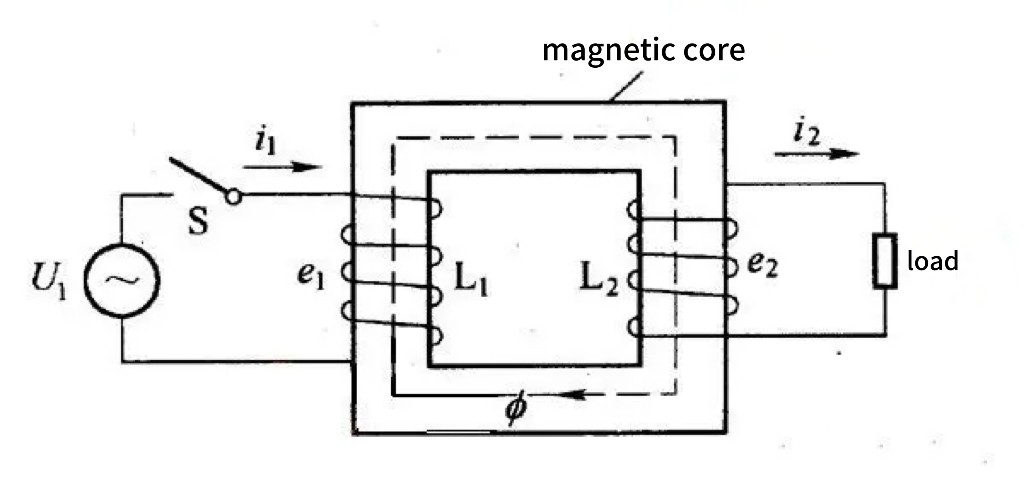
The coil on the input side is called the primary winding, while the coil on the output side is called the secondary winding. Assuming no energy loss or magnetic flux loss, the ratio of voltage between the two sides equals the ratio of the number of turns in the coils, while the current is inversely proportional to the voltage. If the number of turns in the secondary winding is greater than that in the primary winding, it's a step-up transformer; conversely, it's a step-down transformer.
To minimize energy consumption, coils are typically made of highly conductive copper, and the magnetic core is made of iron or iron oxide with good magnetic permeability. To reduce eddy currents generated in the magnetic core, the core can be constructed by stacking mutually insulated laminations of iron.
Under the same conditions, three-phase transformers save materials compared to single-phase transformers.
It's worth noting that this type of transformer can only change voltage, not frequency. For a considerable period of time, transformers like the ones described above were the only type of power conversion devices until the advent of semiconductors.
Before semiconductors emerged, in order to meet other power conversion needs, there was a method of using motors to drive motors. For instance, through gears, using a driven motor with a speed greater or less than the driving motor to achieve frequency conversion; using an AC motor to drive a DC motor for rectification; using a DC motor to drive an AC motor for inversion. Compared to modern semiconductor power conversion technology, this method is both wasteful of materials and increases losses, but it was done out of necessity.
2. Rectifier

A rectifier is a device that converts alternating current (AC) into direct current (DC), and it can be implemented using four diodes.
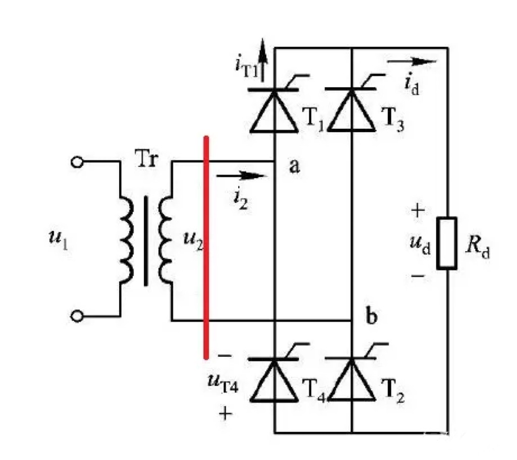
As shown in the diagram, the left side represents the circuit model of the transformer, while the right side represents the circuit model of the rectifier.
On the secondary side of the transformer, when the direction of the AC current is from point “b” to point “a”, the current passes through T1 and returns through T2, with the direction through Rd being from top to bottom. When the direction of the AC current is from point “a” to point “b”, the current passes through T3 and returns through T4, still with the direction through Rd being from top to bottom. This achieves the conversion from AC to DC.
However, the waveform output by the rectifier in the diagram still closely resembles a sinusoidal curve. To reduce ripple and smooth the voltage, a capacitor is typically connected in parallel for filtering. The larger the capacitance, the better the filtering effect.
The voltage on the DC side of the rectifier is √2 times the voltage on the AC side.
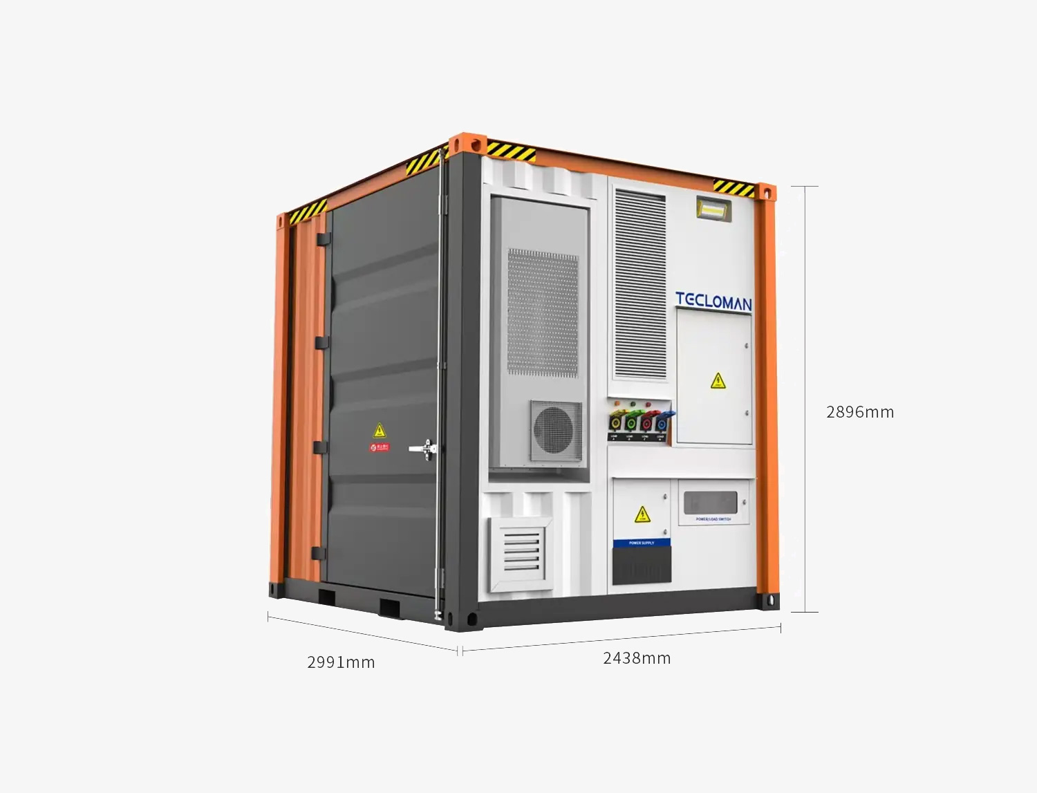
3. Inverter
Tecloman Inverter
An inverter is a device that converts direct current (DC) into alternating current (AC).
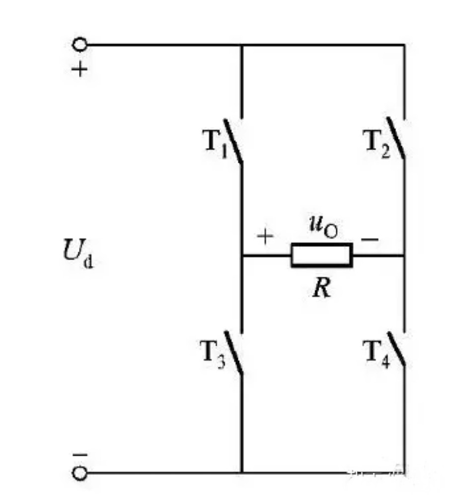
The diagram above illustrates the circuit model of an inverter, where T represents a switch controlled by some signal, and R represents the load. When T1 and T4 are conducting while T2 and T3 are off, u0=Ud; when T1 and T4 are off and T2 and T3 are conducting, u0=-Ud. If we repeat these operations at a frequency "f", the voltage across R will be an AC waveform with a frequency off, as shown in the diagram.
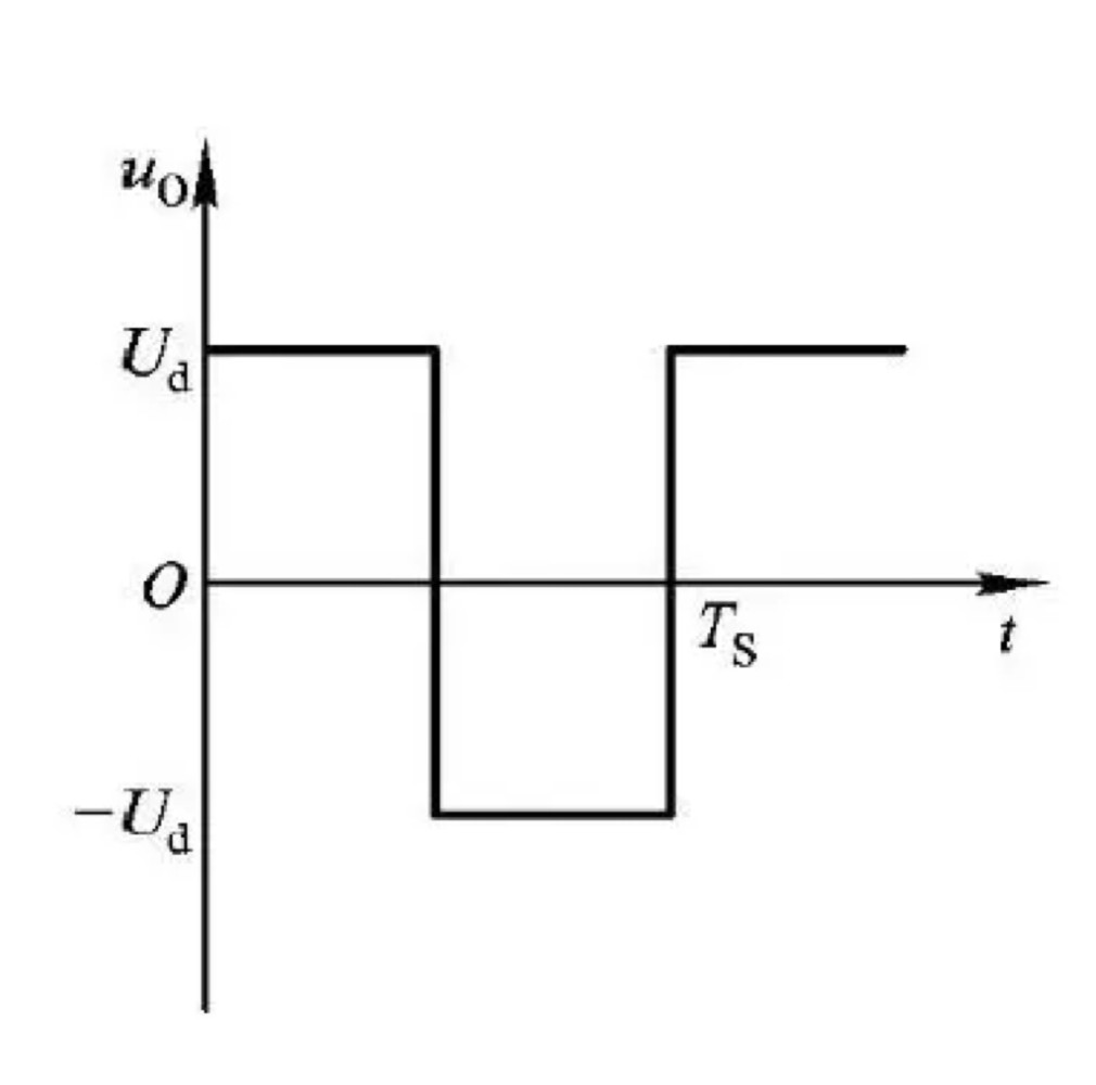
To convert this waveform into sinusoidal AC, a filter (typically a capacitor) can be added at the output.
The voltage on the AC side of the inverter is √2/2 times the voltage on the DC side.
4.Direct Current (DC) to Direct Current (DC) Converter
1)Buck Circuit
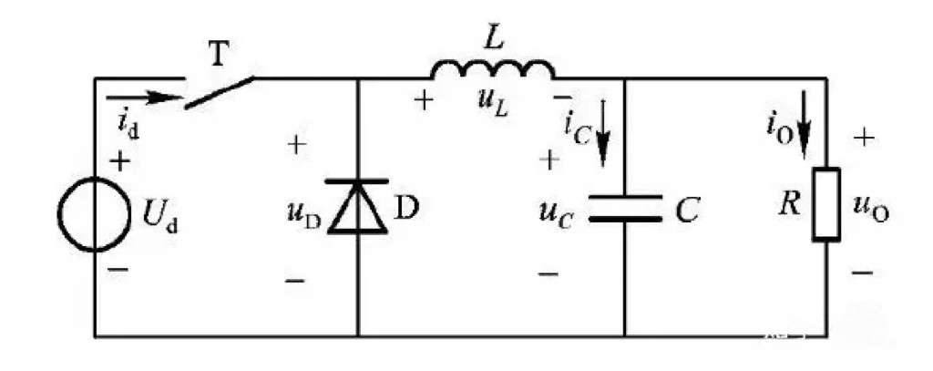
In the diagram, T represents a switch controlled by a certain signal. Let's assume within a period of time t, the switch is on for a duration of t-on and t-off for a duration of t-off, where t = t-on + t-off. This ratio, D = ton/t, is known as the duty cycle.
When the switch T is on, the power supply Ud energizes the load R and charges the inductor L. When T is off, the energy stored in the inductor L supplies power to the load R. The average voltage across R is given by u0 = D * Ud. By varying the duty cycle, the voltage across the load in the circuit can be adjusted. C represents the filtering capacitor, and the larger the value of C, the smaller the ripple on R.
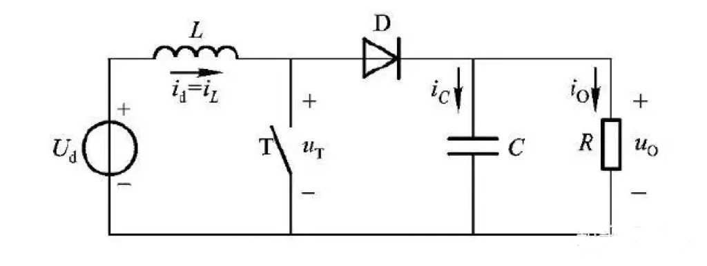
2)Direct Current (DC) Boost Circuit

When the switch T is on, the power supply charges the inductor L, causing the current in L to increase. Simultaneously, the load R is powered by the capacitor C. When T is off, the current in L decreases, charging the capacitor C while supplying power to R. The average voltage across R is given by u0 = Ud / (1 - D), where 0 ≤ D < 1.
3)Buck-Boost Circuit
When the switch T is on, the capacitor C supplies power to the load R, and the current in the inductor L increases. When T is off, the current in L decreases, generating a reverse electromotive force, which charges the capacitor C while also supplying power to R. Therefore, the voltage across R is opposite in direction to the power source, given by u0 = UD / (1 - D).
When 0 ≤ D < 0.5, the circuit functions as a buck circuit (step-down circuit);
when 0.5 < D < 1, the circuit functions as a boost circuit (step-up circuit).

Tecloman Energy Storage
Website:/
Email: info@tecloman.com
Youtube: www.youtube.com/@teclomanenergystorage764
X(Twitter):https://twitter.com/teclomaness